DIY Vacuum Tube Amplifiers
DIY Vacuum Tube Amplifiers
6SN7 Project
Stereo Headphone Amplifier
Design and build by EJ Jurich
This is information on building a low-power ½ watt per channel headphone amplifier. Although ½ watts is not a lot of power, the amplifier will drive more efficient speakers loud enough for casual listening. Speakers with a sensitivity of at least 96 dB @ 1W/1m are recommended. Component costs are moderate compared to most vacuum tube amplifier projects. The most expensive item used to build the amplifier pictured was the custom engraved chassis plate. A standard chassis would be considerably less expensive. The builder is free to use their own layout.
The power consumption of this tube amp is low, measured at 25 watts. With low power consumption, the amplifier puts out moderate heat and can be on for several hours a day without running up a large electric bill. The amplifier was used by the author for several months, and the sound was found to be quite pleasing. The amplifier was given away, and the new owner also found it enjoyable.
6SN7 HEADPHONE AMPLIFIER
with speaker connectors
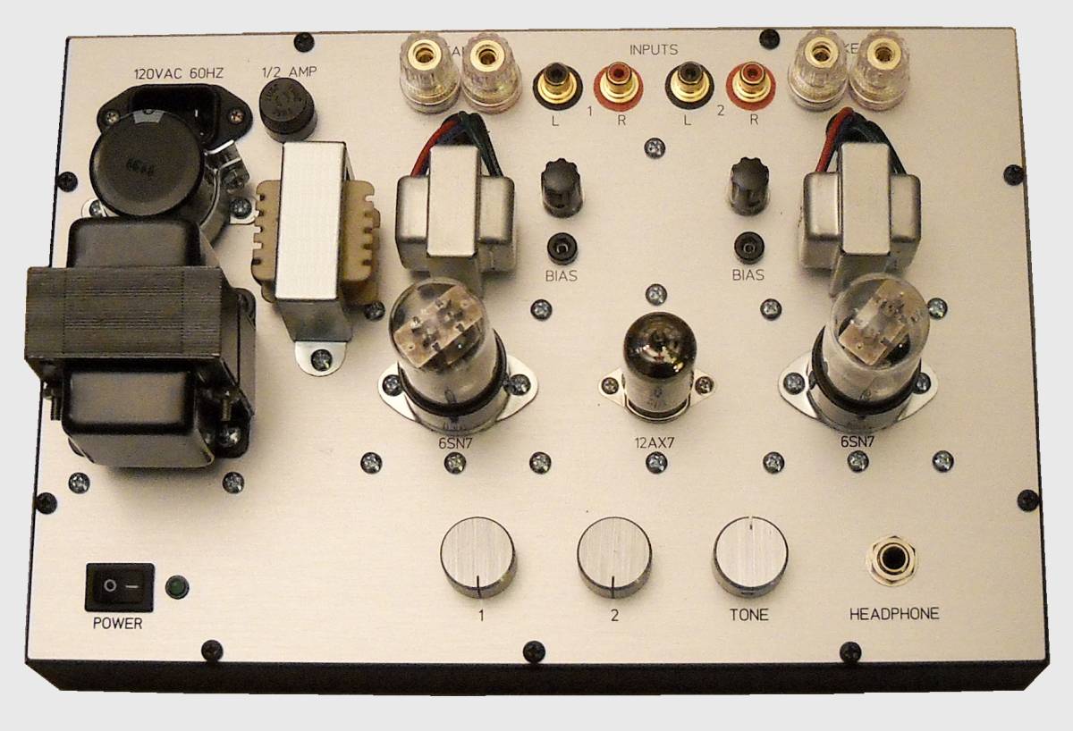
6SN7 HEADPHONE AMPLIFIER
with speaker connectors

This is a stereo two-channel amplifier using three tubes; a 6SN7 in each channel and a 12AX7. Each section of the 12AX7 is used by a channel. There are two inputs; each has its own volume control. The speaker connectors are spaced to accept a two-prong banana plug, allowing the speakers to be disconnected for headphone listening. A speaker switch was not used. Switch contacts can develop corrosion over time, causing distortion to the speaker.
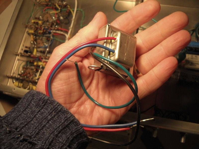
OUTPUT TRANSFORMER

The output transformer is a low-cost P-T1750A replacement originally used as a Fender reverb driver and purchased from tubesandmore.com (Antique Electronic Supply). Choose the P-T1750A 3.5-watt transformer with a 22.8K primary and an 8-ohm secondary. Don't let the small size of the output transformer fool you. Operating at a fraction of its power rating, the small amount of iron in the core is sufficient for a wide response.
The output transformer primary should be wired so the red wire goes to B+ and the blue wire to the 6SN7 plate. In the original 2014 build pictured above, the secondary green wire was ground and the black wire was signal. This is important for the negative feedback to work properly. Leave the output wiring for last. Before soldering output connections, power up the amplifier and experiment by connecting the output and R24/C13 feedback loop. While listening to audio, connecting the feedback loop should cause the audio level to drop slightly. If instead the level goes up, then the output transformer's secondary black and green wires need to be reversed. Work carefully while the amplifier is powered up. Afterwards, unplug the amplifier from AC power, then wait a couple minutes before finishing the wiring. Using a voltmeter, check to be certain the filter capacitors have discharged.
The amplifier uses fixed bias on the 6SN7 output stage. Bias is adjustable, allowing bias to be set for different brands of 6SN7 tubes. The voltage at the 6SN7 output cathode test point should read between .18 VDC and .20 VDC. This corresponds to 9 mA to 10 mA of plate current.
There are two negative feedback loops. The R24/C13 feedback loop helps reduce distortion in the output transformer. The second feedback loop is plate to plate coupling using R23. There is only a few dB of feedback in total.
The input has a high-pass filter comprised of C5, C6, and R9. The roll-off -3 dB point is 40 Hz. The reason for the filter is to prevent extremely low frequencies from distorting the audio. Extremely low frequencies require considerably more power than ½ watt. There is no low frequency control for the same reason. There is a high-frequency control that allows adjusting brilliance. Within its power limits, the amplifier has a sound comparable to a 1955 Hi-Fi amplifier.
HIGH-PASS FILTER RESPONSE
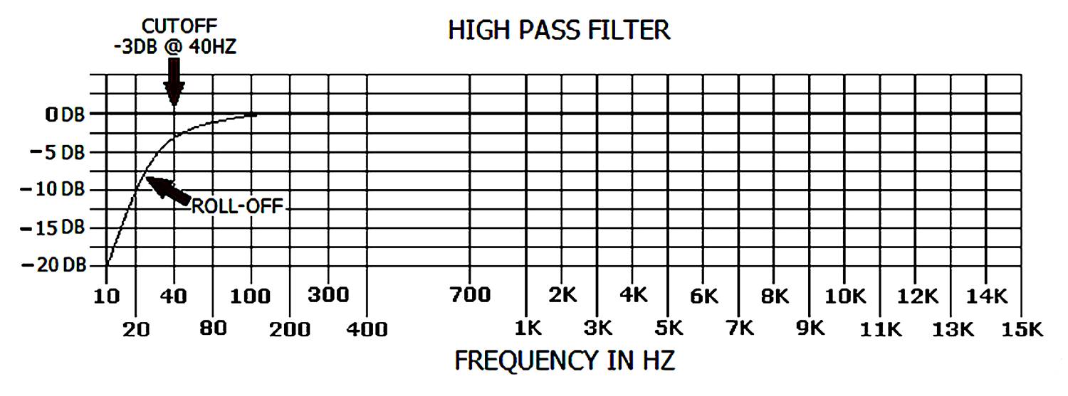
HIGH-PASS FILTER RESPONSE

6SN7 HEADPHONE AMPLIFIER CIRCUIT
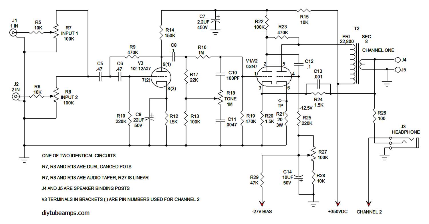
6SN7 HEADPHONE AMPLIFIER CIRCUIT

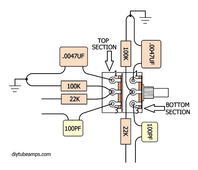

The tone control should be wired in such a way that full counter-clockwise rotation results in a high-end cut (pot wiper at the .0047 uF capacitor). Full clockwise is a high-end boost (pot wiper at the 100 pF capacitor).
The T1 power transformer used was purchased from Allied Electronics under part number 6K88VG. The transformer was built by Hammond for Allied.
Allied is now RS, provider of industrial and electronics products. Prices at RS seem to have doubled and no longer stock components suitable
for Vacuum tube circuits. Use the specifications below to find a replacement transformer.
6K88VG
PRI; 117V, 50/60HZ
SEC; 500 VCT @ 40 mA,
SEC; 6.3 VCT @ 2.0 amps
A close match is a P-T269JX
available from
Antique Electronic Supply
PRI; 115V, 50/60HZ
SEC; 500 VCT @ 69 mA,
6.3 VCT @ 2.5 amps
6SN7 AMPLIFIER POWER SUPPLY
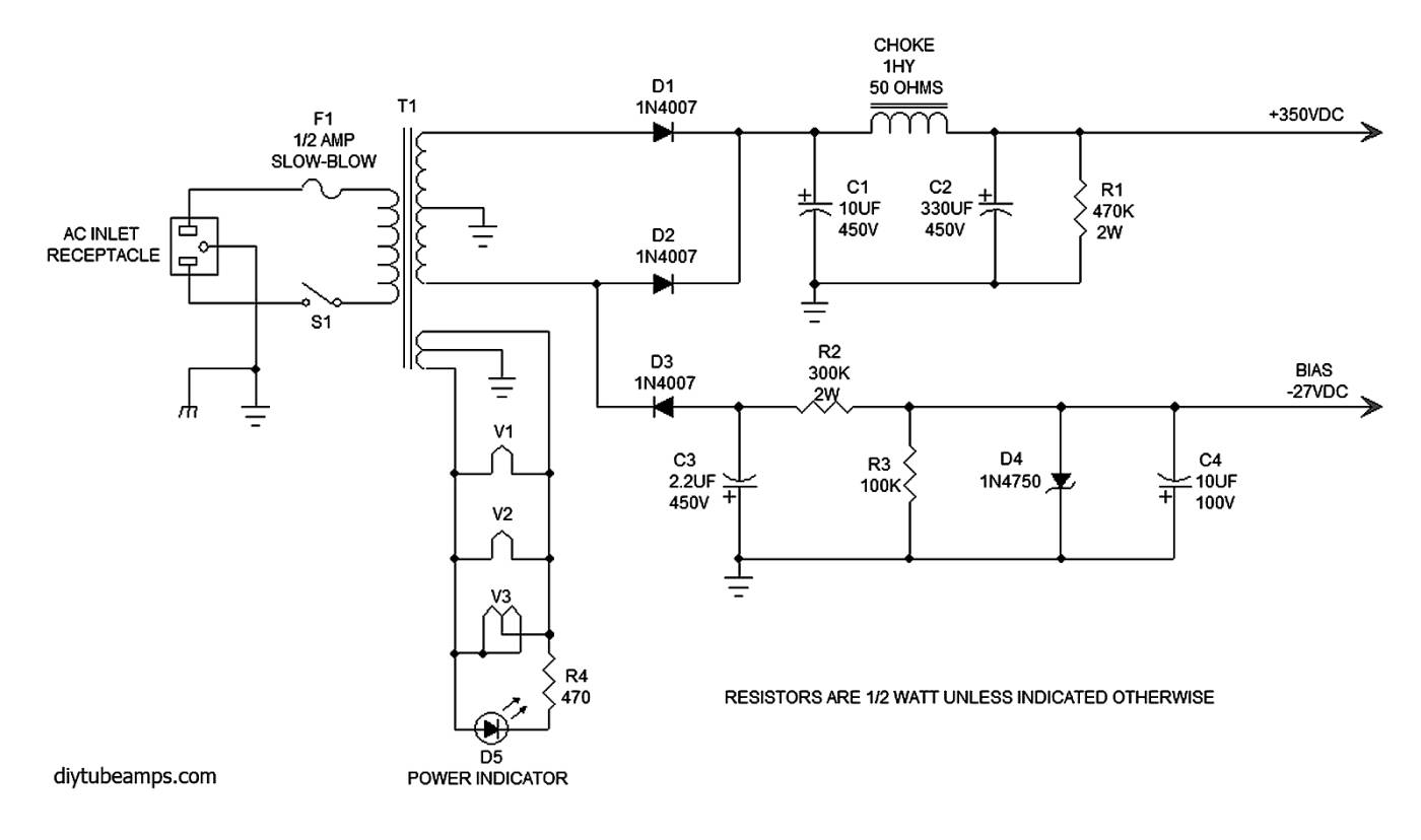
6SN7 AMPLIFIER POWER SUPPLY

6SN7 AMPLIFIER UNDERSIDE WIRING
original build 2014
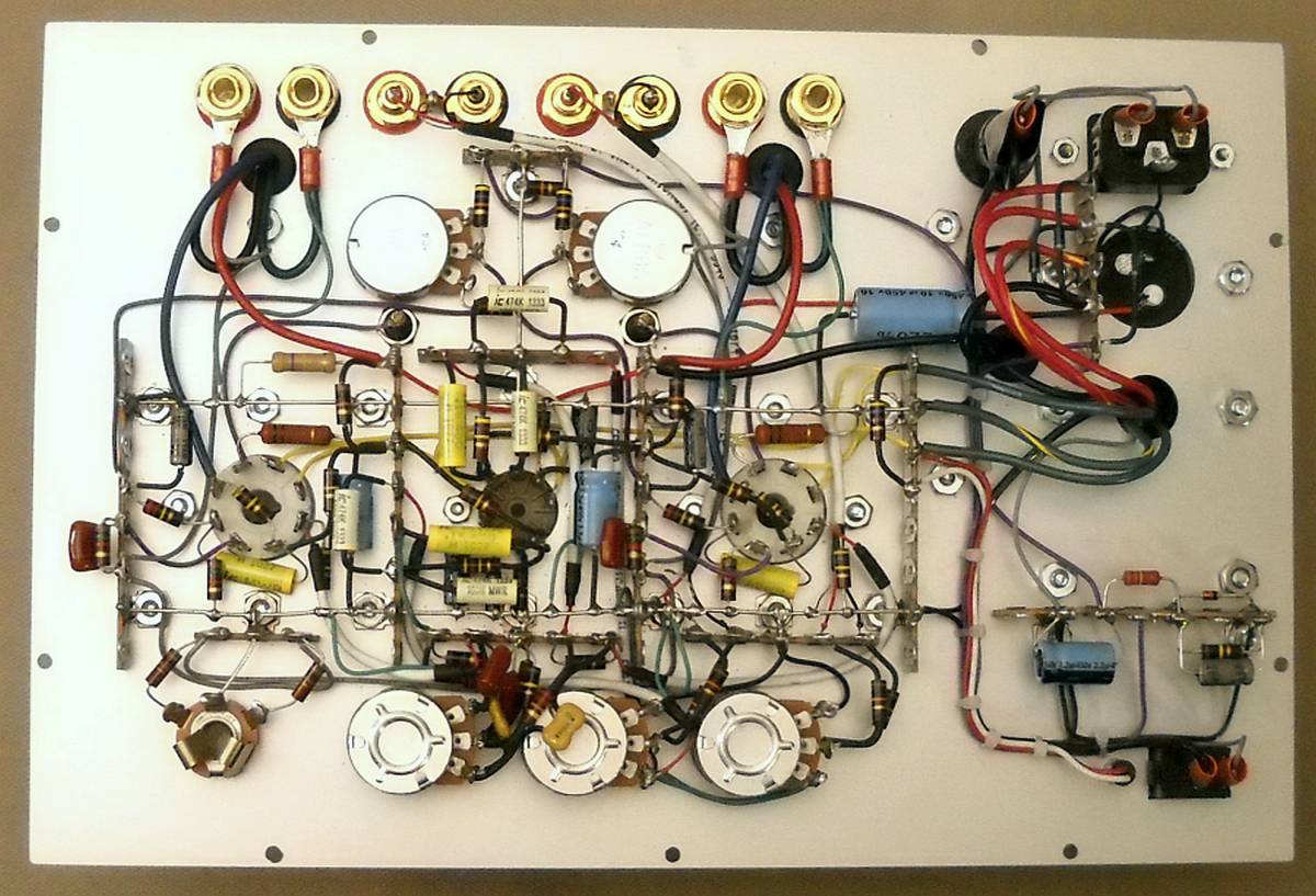
6SN7 AMPLIFIER UNDERSIDE WIRING
original build 2014

Main Page Design For Tube Rolling Vacuum Tube Gain Controlled Amplifier PDF